kuniga.me > NP-Incompleteness > The OSL Shader
The OSL Shader
10 Jul 2011
This last week I managed to make satisfactory progress in the project. First, I implemented the sh_osl shader which is called by the rt application and uses the OSL API.
In the previous post I mentioned that the OSL system required a lot of rays per pixel and that would be a problem when using rt, but I found that an option called hypersampling which solves the issue.
Simplistically, the rt application shoots rays through the rt_shootray() function and calls a callback called shadeview() every time an object is hit. The shadeview() function calls another callback that is associated with the object and corresponds to its shader.
For example, if the target object has the sh_glass shader, then that object has a pointer to the glass_render() function. What the shadeview() function does in this case is call glass_render().
What the glass_render() function or any other *_render() function is supposed to do is essentially return the color of the queried point (passed as a parameter). I will then describe how I implemented the osl_render() function, corresponding to the sh_osl shader.
Reflexion
First, I implemented reflection through a recursive call to the rt_shootray() function, which shoots a new ray in a given direction. This part was easy because the code I had implemented for the standalone raytracer did the same thing.
Figure 1 is the rendering of the Cornell box scene using a mirror OSL shader for the larger box and a “chess” BRL-CAD shader for the smaller box.
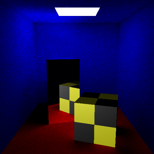
In the end, I didn’t have to take any extra care when mixing OSL and BRL-CAD shaders, contrary to what I had said in the previous post.
Refraction
Implementing refraction was more complicated. First, I discovered that BRL-CAD’s collision detector always calculates two intersection points for each surface. One called inhit, is the point on the surface where the ray initially hits. The other, called outhit, is the ray that went through surface (i.e. refracted).
The osl_render() function is already called with the intersection point P equivalent to inhit, because who sets this is the shadeview(). However, when the ray is refractive (internal) I want P to be the outhit.
So I had to write a new callback to handle refracted rays. Whenever a ray is returned by OSL I check if it is refracted. To do this, just do a dot product between the normal and the new radius to see if they point in “opposite” directions.
If so, I change the callback that will be called the next time an object is hit in the rt_shootray(). What this callback does is set P to outhit and call *_render().
Implementing new shaders for OSL
To verify that the sh_osl() interface is computing the data correctly, I decided to create new shaders that use this data. An example is the checkerboard shader, which uses uv mapping coordinates.
I took the opportunity to implement support for shader groups, mentioned in a previous post, in addition to the possibility of setting parameters via the mged interface.
It is now possible to define a group of shaders through the interface itself. The shader group is then constructed from primitive shaders. For example the shader description:
shadername gen_color#layername#c1#base#color#1.0#0.0#1.0
shadername gen_color#layername#c2#base#color#0.0#1.0#0.0
shadername checker#layername#chk#K#float#4.0
join c1#Cout#chk#Cw
join c2#Cout#chk#Cb
was used in the smaller box, as shown in Figure 3:
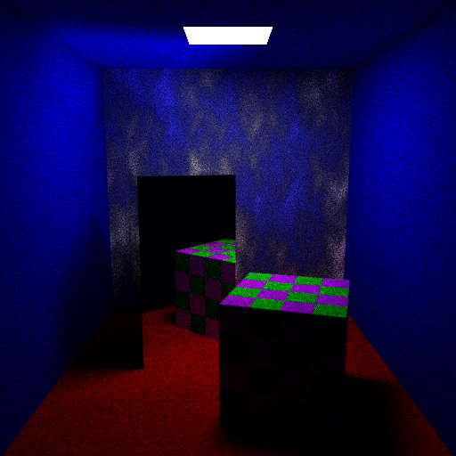
The syntax got a little ugly but it’s functional. The first line describes a generic color shader initialized with magenta color while the second line has green color. The third shader described is the checkerboard shader itself, which uses the output of two other shaders to compose the color of the squares. The fourth and fifth lines deal with connecting the output of the first and second shader to the input of the chess shader. The advantage of describing shaders this way is that if for example I want to compose a checkerboard shader with a green color and a mirror shader I just change it to
shadername mirror#layername#c1
shadername gen_color#layername#c2#base#color#0.0#1.0#0.0
shadername checker#layername#chk#K#float#4.0
join c1#Cout#chk#Cw
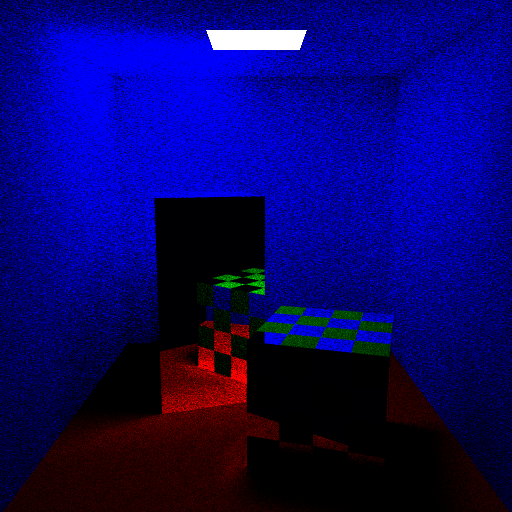
join c2#Cout#chk#CbThat the result will be Figure 4:
Furthermore, the back wall of Figure 3 uses the “cloud” shader adapted from a BRL-CAD shader. It doesn’t look like a cloud at all, but it’s a procedural texture, so we can’t do miracles.
Next steps
I need to resolve the issue of multi-threading. Next week I intend to study how the functions of acquisition and release of resources provided by BRL-CAD work and which resource of the OSL system I need to guarantee exclusive access to.
Later on I would like to implement an incremental view mode. Currently if we want to preview the image as it is rendered, we have to wait for all the sampling to be done for each pixel before seeing it.
My idea is that with each sampling, the whole image is updated, so that initially we see a bunch of scattered pixels and as more and more samples are taken, the image converges to a noiseless one.
Ideally, I would also like to implement an interface for compositing the OSL shader group. The BRL-CAD GUI is written in Tcl, a language that I would have to study before anything else. I don’t think I’ll be able to do that before the show ends, but I intend to do it someday.
Notes
This is a review and translation done in 2023 of my original post in Portuguese: O shader OSL.
