kuniga.me > NP-Incompleteness > OSL Ray Tracer using BRL-CAD structs
OSL Ray Tracer using BRL-CAD structs
26 Jun 2011
I haven’t posted about my BRL-CAD project in a while, but it’s because I haven’t had any interesting results to show. I spent most of the time tackling the more technical aspects of programming, about which I’ve written in recent weeks.
Interface OSL BRL-CAD
I started by writing an interface for the OSL renderer. This interface receives the necessary data about the point $P$ being rendered. This data includes: $P$’s the coordinates, the name of the shader of the surface to which $P$ belongs, the normal of that surface at $P$, and the direction of the incident ray at $P$.
This modularization allows the OSL renderer calculate the color at this point transparently to the application. Conversely, the renderer doesn’t need to know how objects in the scene are manipulated and how intersections are calculated.
One problem is that the OSL renderer may decide that the ray will be reflected (for example if the shader is not fully opaque), but since it doesn’t know anything about the scene being rendered, it has to hand the work back to the application. Therefore, it returns a structure saying whether there was reflection and the direction of the reflected ray. With this new ray, the application will do its calculations and call the interface again.
Testing the interface
Before starting to implement the OSL shader, I decided to test the new interface with an adaptation of that raytracer I talked about in a previous post. Using the same scene, I was able to reproduce the same images. Talking to one of my mentors, it was suggested that I try to render a scene modeled in BRL-CAD using only OSL shaders.
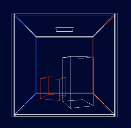
The scene is known as Cornell box. To determine the intersections of a ray with an object, I used the rt_shootray() function provided by BRL-CAD, to which we must pass the origin and direction of the ray in addition to a callback that will be called whenever a ray is hit. I followed this example.
To test it out, I made the walls and ceiling a diffuse blue, the floor a diffuse red, the upper box a diffuse yellow, and the lower box a mirror. The result was the following, with 400 samples:
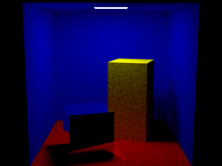
Despite the scene being a little dark, I liked the result.
Next steps
My idea now is to adapt this code to use the OSL shader. I’ve been doing some tests and the task doesn’t seem simple. One problem is that the rt app, which will be using the OSL shader, only shoots one ray per pixel, whereas the above code uses several.
This is necessary because the output ray direction of an OSL shader is probabilistic and it takes a large sample of rays to get the color closest to the expected one.
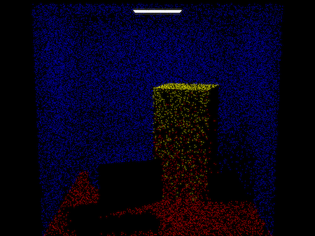
To get an idea, look at the cornell box scene rendered with a low number of samples:
Another issue I’ll have to deal with is mixing BRL-CAD shaders with OSL shaders. Their operating mechanism is a bit different and I will have to study them in more depth to make an eventual adaptation.
Furthermore, I felt more at ease having managed to implement an independent renderer, as this proves to be a more concrete project that I can continue working on and present at the end, in case the implementation of the OSL shader doesn’t work out.
My fear was that I would get stuck with major technical barriers and therefore the project would not be successful.
Final Notes
I got commit access to the BRL-CAD source code. It is quite satisfying to be able to contribute directly to a large code that is used by many people. The community rule is to commit frequently, whenever the code is stable. For now I’ve only made updates to my program and a correction of typos that I found randomly in the code.
Notes
This is a review and translation done in 2022 of my original post in Portuguese: Raytracer OSL usando a estrutura BRL-CAD.
