kuniga.me > NP-Incompleteness > Shaders Written in OSL
Shaders Written in OSL
22 May 2011
I finally figured out what was causing the image to be rendered wrong as mentioned in the previous post. I’m ashamed to admit it, but I was using the old version of the shader that models glass.
Implementation of a new shader
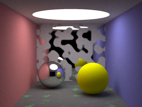
One of the simplest shaders that exists is the one that models a perfectly rough surface, that is, it only has diffuse reflection. The OSL description of such a surface is given by:
// yellow.osl
surface yellow () {
    Ci = color(1.0, 1.0, 0)*diffuse(N);
}
I applied this shader to the sphere on the right, resulting in Figure 1.
Shader Groups
To test the shader group, I created 3 shaders similar to yellow.osl, but with the colors red, green and blue, calling them red.osl, green.osl and blue.osl, respectively. I also created a shader called blender.osl, which takes as a parameter three closure colors and averages them:
// blender.osl
surface blender (
    closure color r = diffuse(N),
    closure color g = diffuse(N),
    closure color b = diffuse(N)){
    Ci = r*(1.0/3) + g*(1.0/3) + b*(1.0/3);
}
When creating the shader group, I declared each shader and connected the output of the color shaders to blender shader. When creating a shader, contrary to the documentation, the current OSL shader system implementation requires passing as a parameter: the shader use case (surface, offset, etc.), the shader name and then the layer name. The gluing is done as as the documentation:
shadingsys->ShaderGroupBegin();
// Declaration of shader layers
shadingsys->Shader("surface", "red", "red1");
shadingsys->Shader("surface", "green", "green1");
shadingsys->Shader("surface", "blue", "blue1");
shadingsys->Shader("surface", "blender", "blender1");
// Connection between shaders
shadingsys->ConnectShaders("red1", "Cout", "blender1", "r");
shadingsys->ConnectShaders("green1", "Cout", "blender1", "g");
shadingsys->ConnectShaders("blue1", "Cout", "blender1", "b");
shadingsys->ShaderGroupEnd();
From my understanding, the resulting closure would be equal to (1.0/3, 1.0/3, 1.0/3) as it is averaging red (1,0,0), green (0,1,0) and blue (0,0,1), that is, the color would be gray.
Applying it to the same sphere on the right, what was my surprise when I saw it with a brown color (Figure 2)!
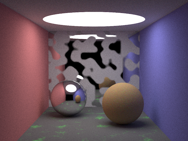
I reviewed the ray tracer code and understood how it works. It’s not that you calculate the resulting color from the closure’s operations. What the shader does is, for each ray hitting the shader, it performs a “random walk” starting at the root of the tree until it reaches a leaf and the color of that ray will be the color calculated so far.
In the example, we start the tree evaluation with w = (1, 1, 1). When going down to the leaf of one of the primitives, we multiply w by 1.0/3, so we get (1.0/3, 1.0/3, 1.0/3). If the primitive in the red.osl is chosen, for example, we multiply it further by (1.0, 0, 0), resulting in (1.0/3, 0, 0).
This means that in practice, the resulting closure returns red, green, or blue with equal probability. If we look at the magnified image, we can see that the sphere is composed of several red, green and blue pixels mixed together.
Next steps
With that, I think I’ve completed the tasks for the period before the start of the project ( the “community bounding” step). Leaving OSL aside for a bit and going back to BRL-CAD, the next tasks to be accomplished in the next two weeks are:
- Implement a new shader for BRL-CAD (suggestions include the zebra or polka dot textures).
- Assign it to an object and render.
Notes
This is a review and translation done in 2022 of my original post in Portuguese: Shaders escritos em OSL.
