kuniga.me > NP-Incompleteness > [Paper] F1: A Distributed SQL Database That Scales
[Paper] F1: A Distributed SQL Database That Scales
10 Feb 2018
In this post we’ll discuss F1: A Distributed SQL Database That Scales. We’ll provide a brief overview of the paper’s contents and study in more details the architecture of the system and the implementation details. At the end, we provide an Appendix to cover some distributed systems and databases concepts mentioned throughout the paper.
F1 is a database used at Google to serve data for the AdWords product. This is the system that displays embedded ads in external pages using Google’s infrastructure.
F1 is named after a term from Genetics, F1 hybrid, in analogy to the idea that it combines the best aspects of relational databases and NoSQL systems (my initial thought was that it was named after Formula One).
In a high-level, F1 is a layer on top of the Spanner database which we covered in a previous post. It adds features such a SQL interface (worth noting that Spanner recently has evolved to support SQL natively too). Spanner handles a lot of the distributed system difficulties under the hood, providing some guarantees and F1 builds relational database features on top of that.
The paper mentions that AdWords migrated from a sharded MySQL solution, which was very expensive to maintain, especially when the data outgrew the instance and re-sharding was necessary. Now, this data redistribution is handled transparently by Spanner and while F1 is theoretically slower, in practice they were able to structure the data in such a way that it’s performant in practice (5-10 ms for reads and 50-150ms for writes).
Architecture
F1 is deployed into multiple servers, across geographically distributed data centers. A client sends requests to a load balancer that then redirects to an F1 server, usually in the closest datacenter.
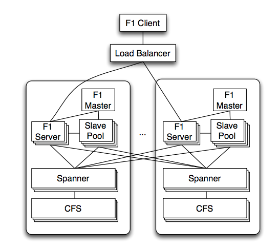
F1 servers are usually in the same Data Center as the Spanner servers that contain their data. F1 can communicate to Spanner servers outside of its datacenter directly, but Spanner only communicates with the Colossus file system (CFS) within the same datacenter because CFS is not globally replicated.
F1 servers are stateless except when the client performs pessimistic transactions, which make them easier to scale, since no data movement is required.
In addition to F1 servers, there are F1 master and a pool of F1 slaves. According to the paper the master controls which processes are in the pool, and that F1 slaves execute part of the query plan on behalf of F1 servers, but it’s not clear why they need to be a separate component.
Data Model
The table data can be organized in a hierarchical schema much like Spanner (see “Data Model” in the post about Spanner). This hierarchical schema is optional but it’s a key piece in making the performance of F1 competitive with the previous sharded MySQL system AdWords used.
In this hierarchy, we have a root table and a child table. For each row in the root table, called root row, we have rows clustered under that row based on their matching keys.
For example, say that we have tables Customer and Campaign. The Customer table has customerID and Campaign (customerID, campaignID). A possible structure for the rows would be:

Where Campaign rows with customerID=3 are clustered together under the corresponding Customer row.
The paper mentions that a given cluster of child rows fall within the same Spanner directory, which means that a transaction would query a single Spanner server, avoiding the overhead of synchronization between multiple servers (see Read-write transactions in the Spanner post).
Indexes. Tables support two types of indexes: local or global. Local index entries are stored in the same Spanner server of the rows the index but it must include the key of the root table. Global indexes do not have such restrictions but they can be distributed across multiple Spanner servers and very expensive to update within a transaction.
Schema changes. Updating the schema of a table is challenging because the rows of the table are distributed, which makes schema consistency expensive to achieve, and the system cannot have downtime.
The proposed solution is to break schema changes into smaller steps, such that as if no 2 severs are more than 2 steps apart, the changes are safe.
Writes
Transactions
F1 supports 3 types of transactions: snapshot transactions, pessimist transactions and optimistic transactions. It relies on the transactions supported by Spanner, so it’s worth re-reading the Implementation Details of the Spanner post.
Snapshot transactions are read-only transactions and map to the corresponding read-only transactions from Spanner. The pessimistic transaction maps to the read-write transactions from Spanner.
The optimistic transaction consists of multiple reads followed by a single write. F1 stores an extra column with the last modified timestamp for each row. When the client performs the reads, it stores the largest timestamp it saw for any row it received. It sends this timestamp together with the final write request. F1 then performs a pessimistic transaction to read only the timestamps of the affected rows. If any of them differ from the timestamp sent by the client, it aborts. Otherwise it performs the write.
It’s worth noting that F1 didn’t create a transaction until the very last write request was sent. It’s assuming there were no writes between these reads and the final write, so we say it’s optimistic. This is the default transaction type and the paper describes a few advantages over the pessimistic type.
Locks
F1 supports very granular locking of the tables, including row level and cell (set of columns for a given row) level.
Change history
F1 stores change history of the data. The changes are stored as regular tables in a structure called ChangeBatch, children of a root table. If a transaction updates multiple root rows, several ChangeBatches are created under their corresponding root tables.
This feature allows clients to subscribe to changes in F1 tables using a publish-subscriber system. Whenever the client receives a notification, it can ask for incremental changes after a specific timestamp and apply to the data it has stored locally.
Reads
F1 supports both NoSQL and SQL interfaces. The SQL dialect was extended to support Protocol Buffers, which are complex data types with strong types (as opposed to loosely typed structures such as JSON). This extension allows, for example, to read and update internal fields of such structures.
Local vs distributed. F1 supports centralized execution (running on a single F1 node) or distributed. The query optimizer decides which one to execute. The paper details the process of executing the query in a distributed fashion.
Distributed Query Example
The paper describes an example of a SQL query being mapped to an execution plan. It involves two joins, filters and aggregations:
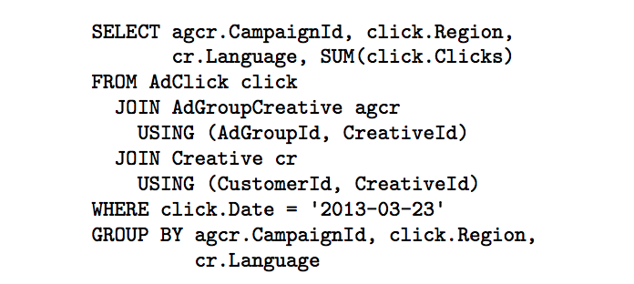
This SQL query is parsed and converted to a query plan that will be executed by multiple machines called operators. A possible execution plan for the sample query is:
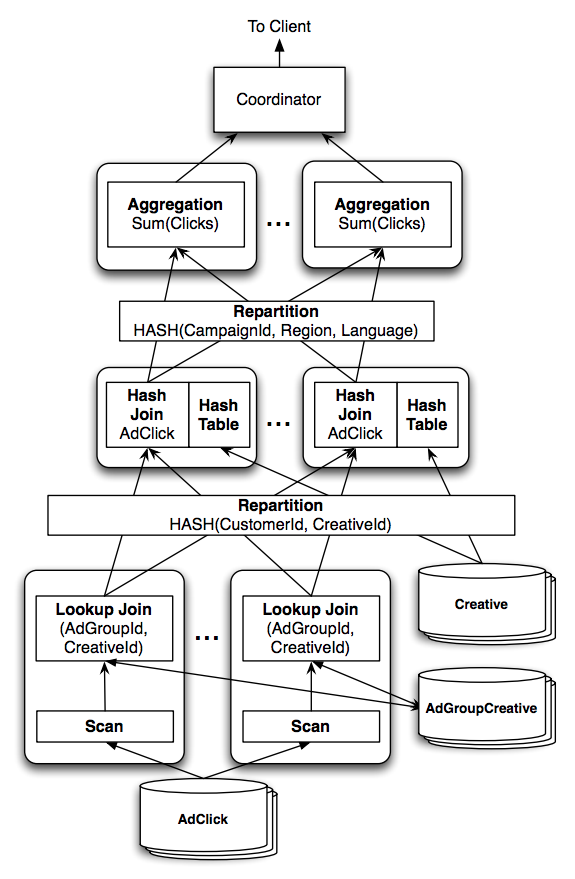
The arrows indicate the data flow, starting at the bottom. The first join is a lookup join (hash join). The operation reads rows from the AdClick table until it has about 100k unique lookup keys stored in a hash table. Then it performs a single (batch) lookup to the other table, AdGroupCreative. The rows from the AdClick table are kept in memory for faster lookup.
As soon as the join for these keys are completed, they’re streamed to the next stage of the pipeline.
The second join with Creative is a distributed join. It first repartitions each row from each table based on the values of the columns listed in the USING clause. Each partition might end up in different machines for the next stage which consists of joining the columns of matching rows.
Finally, the rows are again repartitioned, now by the values from the group by columns and then aggregators apply the aggregation for sets of rows under the same partition.
Distributed Execution Overview
More generally, the query plan created by F1 is a DAG (directed aclyclic graph) where each node is an operator like the join or aggregator described above. Note that there are multiple operators running the same operation in parallel.
The paper says:
A technique frequently used by distributed database systems is to take advantage of an explicit co-partitioning of the stored data.
It’s not very clear to me what they mean with that, especially because they don’t cite any references, but from context it suggests that the base operators (the scan and lookup join) are in the same machine as the data (co-located) and they do as much of the processing upfront as possible. This helps minimize data transfer which can become the bottleneck in a distributed computation. F1 cannot do that because Spanner abstracts the data location from F1.
A side effect is that there’s a lot of network traffic. The authors claim that Google has network switch hardware improvements which allows servers to communicate with each other close to full network speed.
When the hash tables in memory grow too large, they write part of the data to disk. So while F1 doesn’t store data in a persistent way, it still needs to write to disk for intermediate operations.
For efficiency, F1 doesn’t write checkpoints to disk. The downside is that the system is not fault tolerant. Failures in any stage of the execution causes the entire query to fail. Retries are done transparently but long queries (>1h) are bound to fail.
Other features
F1 exposes data from intermediate nodes to clients. This avoid having all the data concentrating at the last node of the query execution. They cite Map-Reduce jobs as examples of such feature.
Conclusion
In this post we learned about one of Google’s many distributed databases, F1. It’s a loosely coupled layer on top of Spanner to provide a more familiar level of abstraction which are relational databases.
It seems that we could make an analogy between Google’s systems and similar open source solutions. The Colossus File System (CFS) is the distributed filesystem that could map to Hadoop Distributed File System (HDFS), and Spanner would map to Hadoop’s YARN, and F1 providing SQL semantics on top of Spanner could be mapped to Hive which does the same for Hadoop. It’s a very rough comparison, and maybe Spanner is more similar to Spark but it’s interesting to see the patterns and relationship between these systems.
References
Appendix: Terminology and Concepts
I was unfamiliar with several of the terminology and concepts used throughout the paper, so I had to do some extra research. Here I attempt to explain some of these topics by quoting snippets from the paper.
We also have a lot of experience with eventual consistency systems at Google
Eventual consistency means that a set of servers might not contain the most recent updates but eventually will. For example, the client might issue a write that affects multiple machines. If the system only provides eventual consistency then a subsequent read is not guaranteed to get the data up-to-date with those writes.
The quote mentions experience with eventual consistency in a negative way, because of the extra complexities that clients have to deal with to work around this limitation.
