kuniga.me > NP-Incompleteness > Shaders for BRL-CAD
Shaders for BRL-CAD
29 May 2011
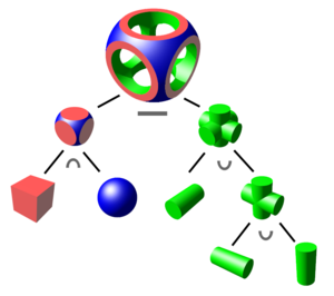
As I said before, BRL-CAD is a modeling software based on constructive solid geometry. This modeling consists of, given a set of basic primitives such as cube, sphere, cylinder, etc., building more complex objects based on operators such as union, intersection and difference.
The advantage of this type of modeling is that the description of the object is very compact, needing only the parameters of the primitives and the operations performed on them. The downside is that the objects that can be constructed this way are quite limited.
Rendering an Object in BRL-CAD
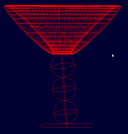
One of the tools in BRL-CAD is called mged. It consists of a terminal and a preview window. In this terminal, the user can type commands to create primitive objects, perform operations between objects, etc. The created objects can be viewed in the other window. Figure 2 highlights the wireframe of a cup created through commands in the terminal.
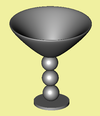
Once modeled, it is possible to render the scene through raytracing. The figure below is a result of rendering with a default texture, the phong shader (models a plastic texture).
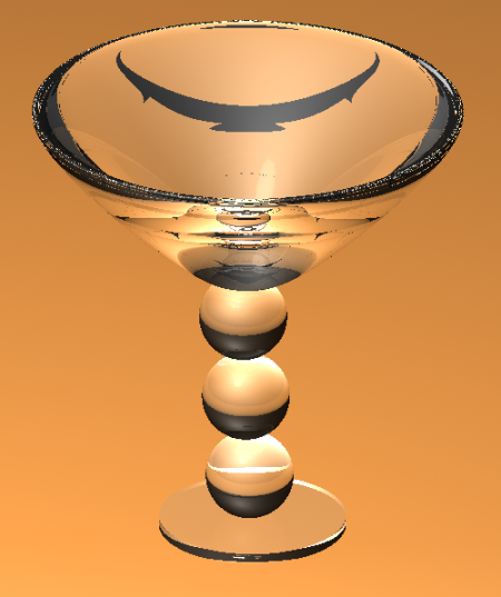
Through the mged interface itself, you can assign shaders to the object. Some of them are: plastic, mirror, glass, plaid, cloud, light, etc. From the little I’ve tried, these shaders aren’t very realistic (or I’m not using them right :P). Figure 4 is an image applying the glass shader to the object, on an orange surface, with a light source and a black background.
Studying BRL-CAD shaders
Now that I’ve learned how to test a shader visually, it’s time to study the code for one of them. The simplest is the null shader, simply because it does nothing! It exists as an example for the interfaces that must be implemented. Most of BRL-CAD, including its shaders, is written in C.
struct mfuncs null_mfuncs[] = {
  {MF_MAGIC, "null", 0, MFI_HIT, 0,
  sh_null_setup, sh_null_render,
  sh_null_print , sh_null_free },

  {MF_MAGIC, "invisible", 0, MFI_HIT, 0,
  sh_null_setup, sh_null_render,
  sh_null_print, sh_null_free },

  {0, (char *)0, 0, 0, 0, 0, 0, 0, 0}
};
Each shader must populate an array of structures like the ones in the code above, and this array must be null-terminated. Each such structure represents an interface to the main program. The second parameter (set with "null" and "invisible" in the example) represents the name by which the shader will be referenced.
The sh_null_setup function will be called at the beginning of the program and should initialize the shader. The sh_null_render function is called each time a ray from the raytracer hits a surface with this shader and must fill the color at the point of intersection. The sh_null_print function is called whenever an error occurs and should print a debug message. Finally, sh_null_free frees up any allocated memory.
If it were in C++, we could define a base class for mfuncs and each element of the array above could be a class derived from it. Notice how sh_null_setup is pretty much what a constructor usually does and sh_null_free does the destructor’s role.
Moving on to a non-trivial shader, I looked at the “Toon Shader” that generates non-photorealistic, cartoon-like images, as shown in Figure 5.

To understand how it works, we have to talk about Lambert’s cosine law.
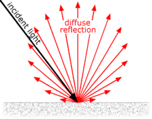
The greater the angle between light and the normal at the point being evaluated, the lower intensity of diffuse light will be reflected. This can be noticed by the gradients in the image of the plastic cup. What the toon shader does is to discretize this gradient by splitting it into buckets. Note that in the figure of the cup with the toon shader, it is possible to see the divisions between the different shades of grey.
Developing a new shader for BRL-CAD
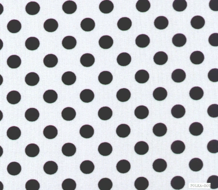
My task was to develop a polka dot or zebra shader. I opted for the polka dot, whose texture resembles those polka dot dresses:
Researching a bit about how to implement such a shader, I discovered one written for another shading language called RenderMan. In it there are two variables s and t that were not passed as a parameter, so I imagine they are global.
Despite the s and t names, it seemed to be related to UV mapping. I had already heard about this when I was messing with Blender. The idea is to map the surface of a 3D object onto a 2D plane. A classic example of this mapping is the projection of the Earth on 2D maps.
As with maps, there are several ways to do the mapping and none of them is necessarily better. In BRL-CAD the mapping is done automatically by the shader system. An existing shader is that of the “chessboard” texture. I rendered the image of the cup with this shader:
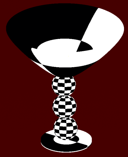
The BRL-CAD shader system provides the u and v coordinates corresponding to the projection onto the plane. What I did was replace these coordinates with the RenderMan shader variables s and t. The result was as follows:
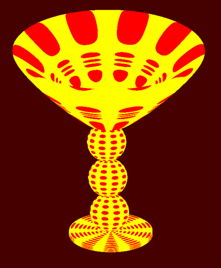
The shader was not good at all. The balls are distorted. However, my project mentors said it was enough. The important thing was that I learned the basics of creating shaders. How to access global variables, how to compile, etc.
Next Steps
Talking with the mentors, we decided that the next step will be to develop a shader to interface with the OSL shader system. I believe that with the knowledge acquired from studying the raytracer using OSL and developing a shader for BRL-CAD, it is possible to accomplish this task.
Notes
This is a review and translation done in 2022 of my original post in Portuguese: Shaders para o BRL-CAD.
